The Branch Tutorial - Texturing
written by André Adam
Summary
In this tutorial we will have an in depth look at how to edit texture coordinates
using the Texture Editor (TE). For this purpose we will texture a polymesh
tree branch seamlessly by creating and editing two individual Texture Projections
and using some blending stuff in the Render Tree later on. You will need to
download this project database in order to do all of the tutorials below.
BranchTutorial_zip. (700k)
The theory behind the Texture Editor
The Texture Editor enables you to unfold polygon meshes "in front"
of the texture to correct distortions that usually appear when you project
textures onto meshes.
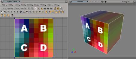
Take a look at the images
below. The first one shows a planar mapping of a cube, including the distortions
on four of it's sides that usually occur. The second one shows the cube unfolded
in the Texture Editor; this way every face of the cube is distortion-free
textured with a separate part of the texture. In this example a wrapping-effect
is enabled, so that every part of the cube located outside of the image will
be texture with the image repeating.

The theory behind samples
Most of the time we will
have to deal with samples in this tutorial. You can think of samples as sub-points.
A regular point on a polymesh object holds as many samples as polygons are
directly connected to it.
Samples hold the texturing
information. This means for every polygon's corner a specific uv coordinate
is stored that precisely defines which part of a texture is "hooked up"
there. Samples are a great thing for storing this information compared to
regular points, because they enable us to tear meshes virtually apart in the
TE and map neighbouring polygons with totally different parts of the texture
without the need of generating additional Texture Projections and Clusters.
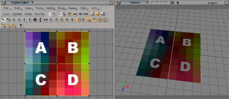
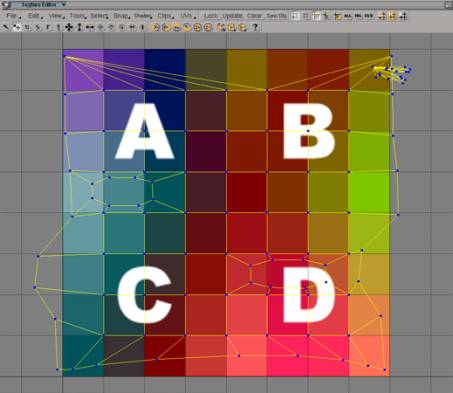
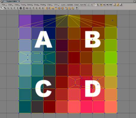
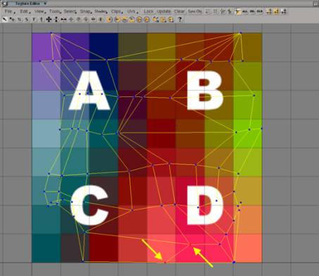
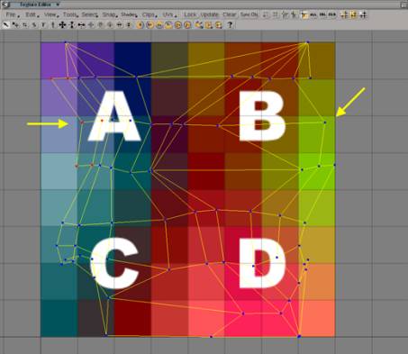
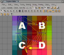
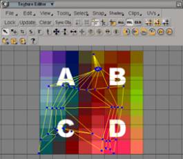
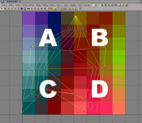
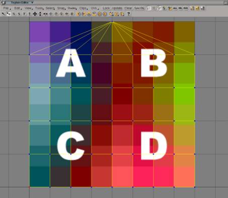
Take a look at the images
below. These are screenshots taken from a TE showing a grid's texturing. The
first one shows a regular planar texturing. In the second image you see that
I moved each polygon's samples differently, this way mapping different parts
of the texture onto neighbouring polygons.

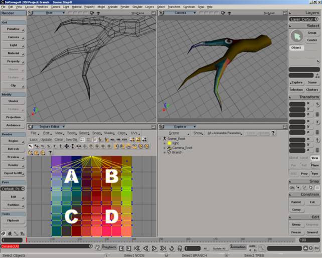
Terminology
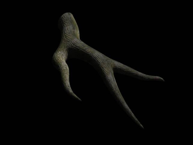
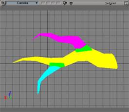
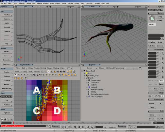
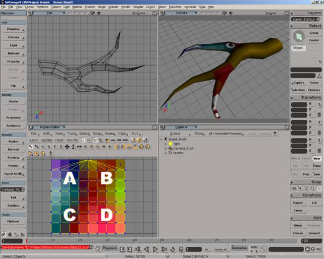
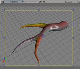
Below you see a screenshot
of the branch we will have to deal with. I will refer to different parts of
it during the tutorial:
The yellow part is the main branch.
The pink part is the first side
branch.
The cyan part is the second side
branch.
The green area is of special interest. In the scenes it is marked with
a cluster. I'll refer to these polygons as the cluster polygons.
Tutorial I: The main branch
1.: Open the "Start"
scene.
2.: Make sure the Texture Editor is unlocked and the Auto
Show Selected option, located in the TE's View
menu, is enabled.
3.: Select the branch object.
4.: Choose Render > Get > Texture > Image. Assign the "Mapper"
image to the branch, located in the project's "Pictures" folder,
and give it a cylindrical Texture Projection.
5.: Make sure the "Mapper" image is displayed in the TE. If not,
choose it manually from the TE's Clips menu.
6.: Rotate the Texture Support
-90 degree in z and scale it locally in y
by 5, so that it fits the branch
better. Note how the TE reflects the changes.
The first things we will take care of is the main branch's mapping. This is
what the Texture Projection we made in step four will solely be used for,
the side branches will get their own Texture Projection later on. We use the
"Mapper" texture for adjusting the UVs before we exchange it with
the "Bark" texture, cause it's much better suited for debugging
UVs.
Take a close look at the cluster polygons. These polygons will make use of
both Texture Projections in the end. It's the area where we will blend the
main branch's and the side branches' texturing together. We don't need the
cluster for that, it's just there for orientation purposes.
7.: In the Top View select all of the main branch's polygons, including the cluster
polygons.
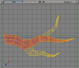
8.: Translate the Texture
Support in y and z until the middle axis fits the main branch as precise as
possible. This should lead to the Texture Projection appearing better unfolded
in the TE. Try rotating the Texture Support in local y to further refine the
unfolding.
Get a feeling of how the
Texture Projection displayed in the TE is affected by your actions. Note that
we will still have to clean things up manually; you won't be able to perfectly
unfold the Texture Projection this way.

9.: Load the "Step8"
scene. From time to time you will have to load a new scene now to follow the
forthcoming steps in this tutorial. They're reflecting the tutorial at different
stages. This is needed since we will do pretty much manual editing that you
will most likely do slightly different, leading to other results than those
discussed in this tutorial.
10.: Select the branch.
11.: As mentioned before, the first Texture Projection is solely needed for
texturing the main branch, so let's get the side branches' samples out of
the way.
![]() Select the side branches' polygons excluding the
cluster polygons and collapse the corresponding samples in the TE using the
Collapse button.
Select the side branches' polygons excluding the
cluster polygons and collapse the corresponding samples in the TE using the
Collapse button.
![]() Move the collapsed samples to the texture's upper right
corner using the Translate Tool.
Move the collapsed samples to the texture's upper right
corner using the Translate Tool.
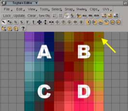
12.: Invert the polygon selection
in the Viewport.
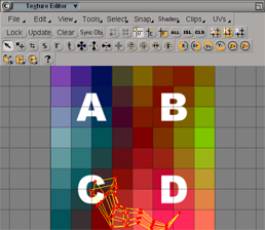
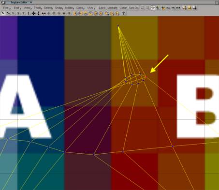
13.: Take a look at the samples
in the TE. You should recognize a grid-like pattern, but there are a couple
of samples at the right side that obviously need to be translated to the left
side.
![]() To do so, deselect all samples in the TE by dragging
in an empty area with the Rectangle Select Tool.
To do so, deselect all samples in the TE by dragging
in an empty area with the Rectangle Select Tool.
![]() Then switch on the Polygon Selection Filter and make sure
Then switch on the Polygon Selection Filter and make sure
![]() Vertex Bleeding is disabled.
Vertex Bleeding is disabled.
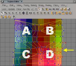
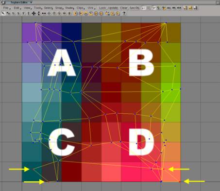
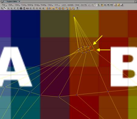
Drag a selection rectangle
touching solely samples of the three polygons that need to be moved using
the Rectangle Select Tool. Note that you only
need to select one sample of a polygon's samples to select all the polygon's
samples when you've activated the Polygon Selection Filter.
![]() 14.: Activate the Translate Tool and move the selected samples
over to the other side.
14.: Activate the Translate Tool and move the selected samples
over to the other side.

![]() Switch back to Vertex Selection Filter and expand the current sample selection by
adding the samples surrounding those of the three polygons we need to fit
to the left side.
Switch back to Vertex Selection Filter and expand the current sample selection by
adding the samples surrounding those of the three polygons we need to fit
to the left side.
![]() Use the Heal function to fit everything into place.
Use the Heal function to fit everything into place.

15.: Load the "Step14"
scene and select the branch.
16.: So, let's move the "repaired" UVs into place to form a uniform
grid structure. First of all get a feeling of how the Vertex
Bleeding mode works.
![]() Activate it and use the Move Component Tool to move a sample on the right border.
Activate it and use the Move Component Tool to move a sample on the right border.
Note how the corresponding
samples on the left side follow this movement; that's
happening because these four samples (you only see two "points"
because each of these "points" actually represents two samples sharing
the same UVs) share the same point in the mesh; that's what Vertex
Bleeding does, moving all samples that share the same point.
Now deactivate Vertex Bleeding and again move a sample on the right border. This
way you can separate samples sharing the same points. Close the gap you just
created by selecting the two samples separated and pressing the Heal button. Note that Heal will only collapse samples that share
the same point in the mesh, if you want to collapse samples of different points
you have to use the Collapse tool.
17.: Use File > Preferences > Grid in the TE's menu bar to adjust the
grid size. Give it a U and V Step of 0.125, representing the 8x8 grid of the main branch. Close the ppg.
In the Snap menu of the TE's menu bar deactivate point snapping and activate
grid snapping instead.
18.: Turn on the Vertex Bleeding mode and activate the
Move Component Tool. Move all inner samples
in place. Use grid snapping where possible by holding down Ctrl while moving the samples.
Note how the side branches'
samples in the upper right corner have moved. That happend because Vertex Bleeding was enabled. Disable Vertex Bleeding, select them and collapse them again.
19.: Ok, what's left a are the border samples. Since Vertex
Bleeding will give bad results with these (this would also move the samples
on the oppsite side), we will have to select them one after the other and
use the Translate Tool while holding down Ctrl to snap them into place. You will
find the Translate Tool's "v"
shortcut handy for this.
After adjusting the light
a bit you can see that the texture runs precisely over the main branch now.

Tutorial II: The side branches
20.: Load the "Step19" scene.
21.: In the Explorer take a look at the branch's Texture Projection located
at Branch > Polygon Mesh > Clusters
> Texture_Coordinates_AUTO > Texture_Projection. All our translate
operations done in the TE have been stored here, so it's definately time to
get rid of this huge operator stack by freezing the object. Use Edit
> Freeze to do so while the object is selected.
22.: Now we're going to texture the first side branch. We will use a second
Texture Projection for this, use Get > Property > Texture Projection
> XZ to assign it to the object.
23.: Select the branch and switch to the new Texture Projection called "Texture_Projection1"
in the TE's UVs menu. This is the
place from where you can choose the Texture Projection you want to work with.
24.: Select the first side branch's polygons, including the cluster polygons,
to isolate their samples in the TE.

Since we created a planar
Texture Projection, the samples are far from being well unfolded. We'll use
a Cylindrical Subprojection to help us with
this.
Subprojections connect selected
samples' UVs to a "faked" Texture Support, which enables you to
move them around and unfold them just like you're used to do with a regular
Texture Projection. The advantage of using Subprojections is that they actually
don't create a new Texture Projection; they act as modifier for an existing
one.
![]() 25.: Create a Cylindrical Subprojection for the selected samples, choose the Best Fit option.
25.: Create a Cylindrical Subprojection for the selected samples, choose the Best Fit option.
26.: Move and rotate the
Subprojection's Texture Support slightly around until you get a good starting
point for manual editing, just like you did before with the main branch. Note
that the side branches are more tricky than the main branch was; their geometry
is pretty far away from a perfect cylinder.

27.: Load the "Step
26" scene and select the branch and switch to "Texture_Projection1"
in the TE's UVs menu.
28.: Before we start to manually unfold the first side branch, let's get the
main branch's samples out of the way, just like we did for the first Texture
Projection with the side branches.
Select the main branch's
polygons excluding those marked with the cluster und collapse their samples.
Move them in the upper right
corner of the image so that they're out of the way.

29.: Again select the first
side branch's polygons. In the TE take a look at the samples near the bottom.
That's a mess. Select the four samples like shown below and use the Heal function to clean things up a bit.
That's much better, we see
the grid-like structure now. Continue by moving the samples on the upper left
side in place on the right side as you did previously for the other Texture
Projection.
30.: Readjust the TE's grid
in v to represent the seven segments of the
side branch by using the File >
Preferences > Grid menu in the TE's menu bar. Just type in 1 / 7 for the V Step to make XSI calculate the right spacing.
31.: Now use grid snapping as before to fit everything in place. Note that
you will perhaps have to turn grid snapping on again in the TE's Snap
menu.

32.: When you've finished,
freeze the object to get rid of the Texture Projection's operator stack.
Take a look at your work. The first side branch is nicely textured now.
33.: Ok, let's move on to
the second side branch to finish the unfolding. Open the "Step32"
scene and select the branch.
In the TE's UVs menu switch to "Texture_Projection1".
Disable Vertex Bleeding and
![]() turn on Island Selection mode.
turn on Island Selection mode.
This mode lets you select
a whole group of connected samples in the TE. This way select the second side
branch's samples.
![]() Finally use the Show Selected option to hide all unselected samples.
Finally use the Show Selected option to hide all unselected samples.
34.: Assign a Cylindrical Subprojection to the selected samples using the Best Fit option. Move the Texture Support
around as you did previously for the first side branch until you get acceptable
results. Due to the sharp bending of this side branch, we're not able to completely
unfold it this way, the top-most samples will stay together.
35.: Load the "Step34"
scene, select the branch and switch to "Texture_Projection1"
in the TE's UVs menu and use the
Island Selection mode to isolate the second
side branch's samples as you did before.
36.: First thing we notice is that we need to rotate the samples by 180 degree.
Do so by using the Rotate by 90 cw tool in the Tools menu two times.
37.: Use the Pan and Zoom Tool (Shortcut: z) to have a closer look at the top-most
samples. All samples there are still connected, representing the actual geometry
of the object. We need to find a good point to tear this apart. The point
most to the right is the correct starting point.
Make sure Vertex Bleeding is turned off and use the Move Component Tool to separate the four samples sharing this position.
Use the Heal function two times, each time with two of the four samples to
collapse them to two positions to form the grid-like structure we need.

38.: Further unfold the samples
by moving them so that we see the grid-like structure better.
39.: Adjust the grid's V Step to represent the five segments
of the branch by assigning it a value of 0.2
and make sure grid snapping is enabled in the TE's Snap menu.
40.: Now move everything in place as usual.
41.: Select the branch object
and freeze it.
Take a look at your work in the Viewport. You have two perfectly textured
side branches now.
Switch to the other Texture
Projection by selecting "Texture_Projection"
in the TE's UVs menu and watch
the Viewport updating. Switch forth and back a few times to get a good idea
of what we've made each Texture Projection for.
Tutorial III: Blending in the Render Tree
42.: Load the "Step41" scene and select the branch.
43.: Open a Render Tree and press Update.
44.: Use Nodes > Texture > Image to get a second Image node.
Connect it to both mixer's
color2 inputs.
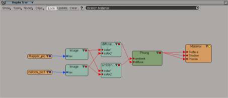
Toggle on the In Use button in both mixers for the second layer.
Open the new Image node and assign it the "Texture_Projection1"
Texture Projection.
45.: Draw a Render Region.
Currently both textures are blended equaly. We have to create some weight
information for plugging into the mixers to get the desired effect. We'll
use Vertex Colors for this.
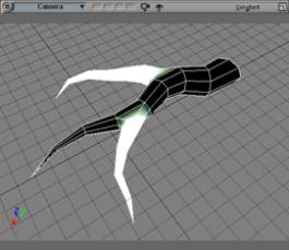
46.: With the object selected use Render > Get > Property > Color at
Vertices to assign a vertex color property and turn Viewport B to Constant display mode.
47.: Open the brush properties using Render
> Get > Property > Brush Properties... , enter the Vertex
color painting tab and toggle on the Vertex
and Polygon options in the Bleeding section.
48.: Get a vertex color brush using Render > Get > Property > Pain Vertex
Color Tool.
49.: Paint the side branches with bright white without directly painting at
the cluster polygons. This should lead to the white color bleeding into the
cluster polygons.
50.: Change the Brush Color to be black and paint the main branch, again without directly
painting the cluster polygons.
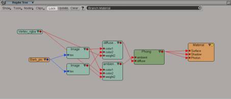
51.: In the Render Tree connect
a VertexRGBA shader, available through the
Nodes > Texture menu, to each
mixer's weight2 input. This makes
the vertex color information available to mental ray.
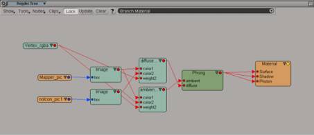
Draw a Render Region to see how the blending did change.
52.: Now it's time to exchange
the textures with something more tree-like. For each Image node pick the "Bark.pic" image, found in the Project's
"Pictures" directory.

53.: Not very good looking
yet. We have to adjust the texture repeats. Do so by entering each Image node's Advanced tab.
In the Repeats section type in
3 in the first line and 6 in the second line for the first Image node, 2 and 4 for the second
Image node. These values represent U and
V repeats.
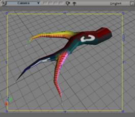
54.: Again draw a Render Region.

That's much better now. Time
to turn the branch into a Subdivision Surface. Do so by applying a local Geometry
Approximation property using Render
> Get > Property > Geometry Approximation. In the Polygon Mesh tab raise the Mesh
Subdivision Level to 2.

55.: That's it. We've seamlessly
textured the branch. If you want to you can play around with some displacement
mapping now to enhance the look with some structure. Refer to the "Displaced"
scene if you like to.
